Full Wave Bridge Rectifier Circuit Diagram and Working Principle Learn how to convert AC voltage into DC voltage using four diodes in a bridge configuration. See the circuit diagram, waveforms, formula, advantages, and disadvantages of full wave bridge rectifier.
Learn how to convert both half cycles of AC to DC using a bridge rectifier with 4 diodes. See the circuit diagram, input and output waveforms, and analysis of peak current, output current, DC voltage, and ripple factor.

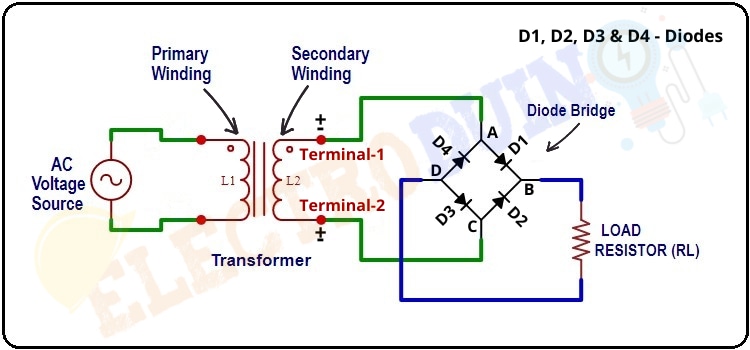
Diode Bridge: Four Diodes That Convert From AC to DC Circuit Diagram
Learn how to use four diodes to convert AC to DC with a diode bridge rectifier circuit. See the diagram, how it works, and what it's used for in power supplies and other circuits. Learn how to convert AC to DC using a bridge rectifier, a type of full-wave rectifier with four diodes in a bridge circuit. See the diagram, waveforms, characteristics, efficiency, advantages and disadvantages of bridge rectifier.
Learn how to convert AC to DC using a bridge rectifier, a circuit made of four diodes arranged in a bridge configuration. See the circuit diagram, waveform, and operation of a bridge rectifier and its applications in various electronic systems.
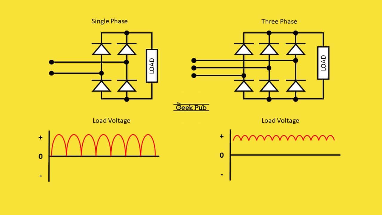
Bridge Rectifier Circuit Diagram And Waveform
A bridge rectifier diagram is similar, to a representation that illustrates the arrangement of components within a specific circuit. Its purpose is to convert alternating AC which is characterized by wave patterns into direct current (DC) that provides a consistent flow of electricity.