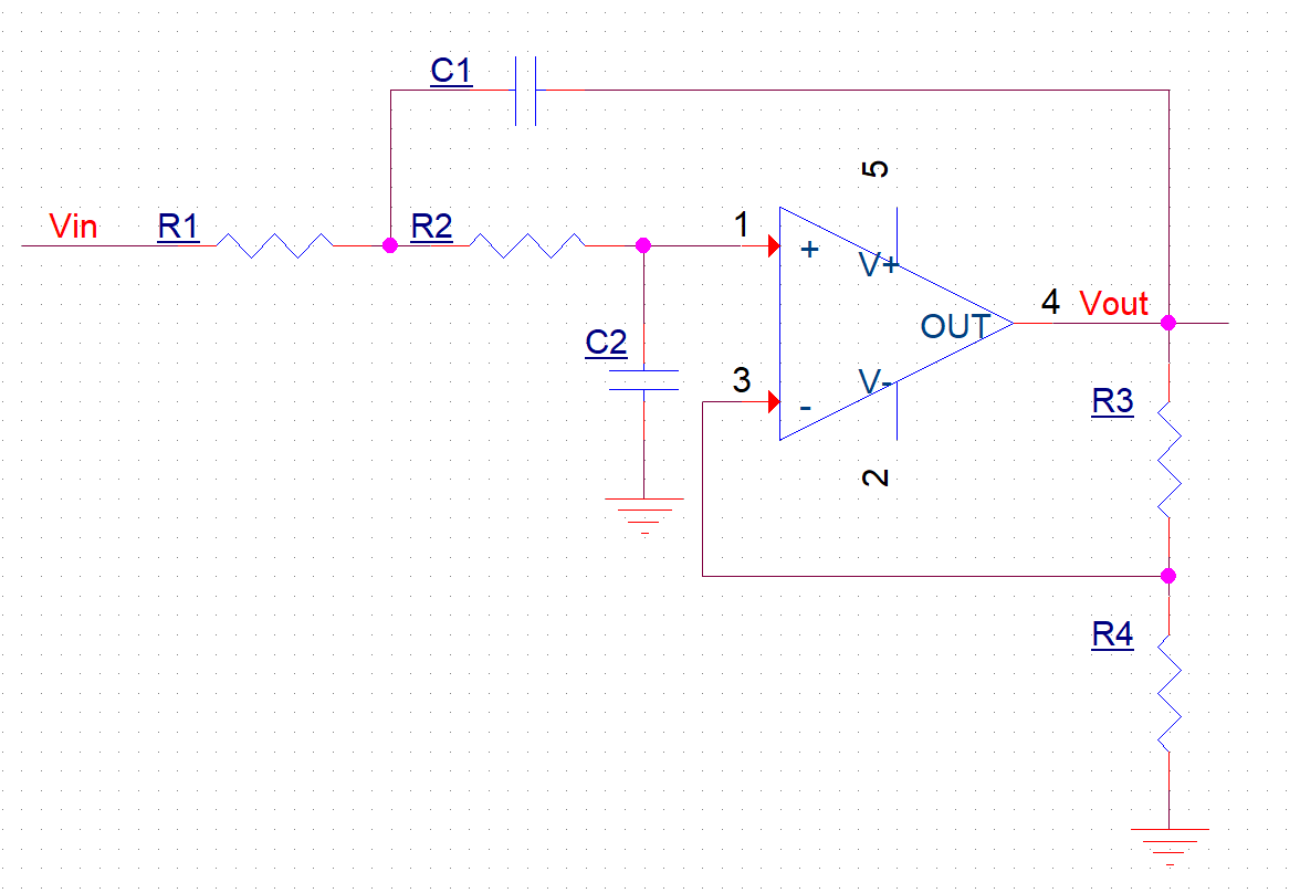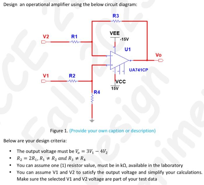
Solved Design an operational amplifier using the below Circuit Diagram
Solved Design an operational amplifier using the below Circuit Diagram Op-amp Basics (part 1): Operational
0 Comments
Wander Everywhere, Find Inspiration Zeke Grant.